Knowledge Center
- Downloads
- Technical Newsletter
- Recommended Guidelines and References
- Specifications
- Technical Papers
- Tools and Calculators
- Training
- Articles, Tips and Requirements
- An Integrated Approach to Manage Vibration Risks
- Design Requirements for Reciprocating Compressors
- Evaluating Compressor Operating Risks
- Five simple methods to check reciprocating compressor performance
- Important Differences in Pulsation Software
- Liquid Pumping Systems (Including Liquid Pipelines)
- Noise Regulations Around the World
- Noise Risks in the Gas Industry
- Performance Monitoring Examples
- Pipe Support Stiffness, GMRC Project
- Piping Vibration Design Considerations
- Piping Vibration Examples
- Structural Vibration and Ways to Avoid It
- Tips for a Successful Project (Vibration Control)
- Transient Conditions on Small-Bore Piping
- Vendor Requirements for Piping Vibration & Integrity Assessment
- Vibration-induced fatigue (whitepaper)
- Vibration Issues Affecting Gas Compressor Facilities
- Ask the expert
Structural Vibration and Ways to Avoid It
(Platforms, FPSOs)
Dynamic loadings take many forms. Two parameters can characterize such loadings: Their magnitude and their frequency content. Dynamic loadings can be replaced by static loadings when their frequency content is low compared to the natural frequency of the structure on which they are applied. Some people will refer as quasi-static analysis or loadings to remind themselves that they are actually predicting the effect of dynamic loadings treated as static equivalent. Most environmental loads (winds, earthquake, wave, transportation) can be replaced by quasi-static equivalents.
Contents [ hide ]
- 1 Structural Dynamic Analysis
- 2 Structural Vibration and Resonance
- 3 Examples of Structural Resonance
- 4 Structural Vibration Analysis vs. Static Analysis
- 5 Optimized Design Approach Reduces Weight, Costs and Avoids Resonance
- 6 Integration of Structural Dynamics with Skid Dynamics and Machinery System
- 7 Summary
- 8 Contact an Expert
- 8 Related Services and Information
1 Structural Dynamic Analysis
When the frequency content of a dynamic loading and the natural frequencies of a structure are in the same range, then this approximation is no longer valid. This is the case for most machinery (compressors, pumps, engines, etc.) which produce loadings whose frequency content overlaps the natural frequencies of the structure on which they are mounted (platform, FPSO, etc.). In such a case, only a dynamic analysis will accurately predict the amplification of the response of the structure. Such loadings cannot be replaced by quasi-static equivalents.
What makes these analyses even more challenging is the fact that the machinery, its equipment and the mounting skid cannot be seen as black boxes. They will interact with the foundation, the platform or the FPSO and the only way to know the magnitude of this interaction is to conduct a structural dynamic analysis that includes the foundation. This is a critical consideration which when overlooked considerably reduces the reliability of the machine and might even cause safety concerns.
2 Structural Vibration and Resonance
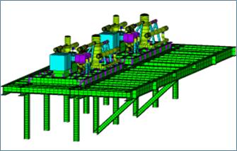 |
| Figure 1: Resonance and vibration on offshore structures is a common problem |
Structural vibration occurs when dynamic forces generated by compressors, pumps, and engines cause the deck beams to vibrate. This vibration leads to piping failures, poor equipment reliability, and safety concerns. The vibration is due to the structure being mechanically resonant. The term “resonance” occurs when dynamic forces coincide with the natural frequencies of the supporting structure. At resonance, the forces are amplified up to 20 times, and cause deck beams to vibrate above safe operating limits.
Refer to Wood's (BETA Machinery Analysis) Training Tools module 1 (video)for a more detailed explanation of resonance.
Structural resonance problems are not limited to larger horsepower equipment. They also occur with smaller reciprocating pumps or compressors, as the examples presented below clearly illustrate. Structural resonance is best avoided by a properly conducted Structural Vibration and Dynamic Design Analysis
3 Examples of Structural Resonance
Structural resonance is a common problem, but avoidable. These and many other examples illustrate structural vibration and resonance problems and methods used to avoid structural vibration (contact Wood for details):
-
Example 1: 750 HP fuel gas booster compressor. Structural vibration is 10 times allowable vibration guidelines, even with very large deck girders supporting this skid (figure 2)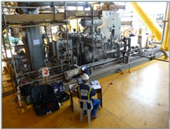
Figure 2: Field testing for vibration on skid and structural beams 
Figure 3: Evaluating storm loading is one example of a Quasi-Static Analysis. Courtesy Shell International Limited - Example 2: Small pump system caused resonance, vibration and continual failure of drive train components on affecting reliability on a critical process.
- Example 3: Brownfield project involving the installation of new compressors on an existing platform. This successful installation illustrates the technical requirements involved in the design and field commissioning for offshore projects.
- Example 4: FPSO with three large compressors mounted on one module. This case study illustrates the integrated approach between compressor skid dynamics and the structural dynamic analysis.
4 Structural Vibration Analysis vs. Static Analysis
Static, Quasi-Static, and Structural Vibration (Dynamic) Analyses are recommended for offshore production facilities. Since these terms can be confusing, this section explains the differences and who should be involved in the evaluation.
Static Analysis focuses on evaluating stress and buckling of members under constant loads. Constant loads can also be described as loads applied at a frequency of 0 Hertz (Hz). This type of analysis can also focus on deflection of skid members as they can affect alignment of equipment.
Quasi-Static Analysis evaluates the effects of loads that are periodic, but at a low enough frequency relative to the natural frequencies of the equipment package so that the inertia effects of the structure do not come into play. They tend to have a frequency of less than 3 cycles per second or 3 Hz.
Structural Vibration (Dynamic) Analysis predicts the dynamic effects of the machinery itself so that resonance can be avoided. Dynamic loads include imbalance, misalignment, pulsation forces, cross-head guide forces, cylinder gas forces, moments, and other forces (see Figure 5 for an example of dynamic forces in a reciprocating compressor). The machinery related loads occur across different frequency bands and can cause localized structural resonance.
Structural Dynamic Analysis focuses on evaluating vibration levels and stress. Limiting vibrations of structural members is important to control vibration of the equipment, vessels, and piping that are attached to it. If a skid member has high vibrations then these components will likely experience high vibrations also.
The applicable load frequency ranges and the associated design criteria for these three types of analysis are presented in Figure 4 and Table 1 (below).
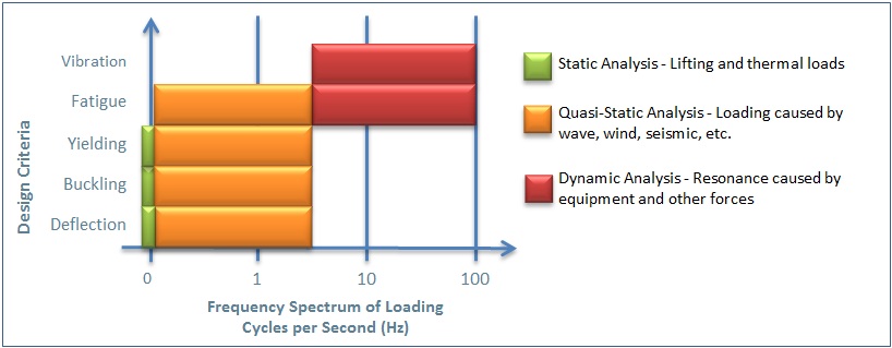 |
| Figure 4: Design criteria for static, quasi-static, dynamic analysis |
| Table 1: Comparison of Structural Design Studies | ||
|---|---|---|
| Static Analysis | Quasi-Static Analysis | Vibration (Dynamic) Analysis |
|
Loads:
|
Loads:
|
Loads – Example from a reciprocating compressor (other loads occur in pumps):
|
5 Optimized Design Approach Reduces Weight, Costs and Avoids Resonance
One common industry approach is to increase the size and location of the deck beams. This approach can add significant construction costs and weight to the facility – beyond what is practical. It is also provides no guarantee that resonance will be avoided.
The recommended approach for dynamic analysis is to prepare an accurate Finite Element (FE) model of the dynamic load, skid, and affected structural members. Over the years, Wood has developed a number of specialized techniques to ensure accurate FE models. The approved model, combined with the dynamic forces, is used to identify local resonances and evaluate possible solutions.
Designing the structural steel supports for a compressor or pump package must balance stiffness, mass, and cost. High stiffness will help avoid vibration problems, but excessive use of over-sized beams will affect the mass and cost. An optimized design identifies where steel can be added or removed at key locations to maximize the stiffness and minimize the costs. This optimized approach will provide significant cost savings to the owner – far in excess of the cost of the engineering time.
6 Integration of Structural Dynamics with Skid Dynamics and Machinery System
During the design process, the structural engineers will conduct the Static Analysis. A specialist in Dynamic Analysis, such as Wood, conducts the Structural Vibration Analysis because it is integrated with the Dynamic Skid Analysis, and the dynamic modeling of compressor/pump systems.
There are many reasons why a specialist vibration/dynamic engineering company (such as Wood) is mandated to complete the Structural Dynamic Analysis:
- The evaluation is dependent upon accurate understanding of the dynamic forces from the machinery (frequency, amplitude, changes by operating condition, etc.). These forces are determined in pulsation studies, mechanical analysis, and other evaluations that are not conducted by Structural Engineers.
- The dynamic FE model has many modifications and changes compared to the static model. These modifications are based on field testing of platforms and FPSO modules utilizing shaker test equipment, dynamic vibration studies, and other field measurements. Applying field results to FE models is needed to ensure accurate results. Wood has decades of field based dynamic analysis that results in better design assessments and more accurate calculations.
- Proper boundary condition assumptions are needed for accurate results. Two identical units on a platform might behave completely differently when subjected to dynamic loads. This is because the flexibility of the support structure influences their dynamic behavior. The skid and machinery dynamic studies are integrated with the deck model to ensure accurate boundary conditions.
- Based on our experience, the FE model created in ANSYS or equivalent simulation software is required. To improve analysis efficiency, Wood has developed techniques to translate the structural model into the dynamic modeling software.
Costly problems have occurred when a simplified approach is used for Structural Dynamic Analysis. Based on numerous field experiences, Wood has developed an accurate and cost-effective approach for new or brownfield offshore projects.
7 Summary
Structural resonance is a common problem on offshore production facilities that causes vibration related failures on piping and machinery systems.
Once the facility is built, it is very expensive to modify the structural deck beams to fix a vibration problem. A better approach is to conduct a Structural Vibration Analysis of specific areas of the deck or platform. During the design phase it is easy to make minor changes to the beam orientation and design to avoid resonance. This dynamic analysis is coordinated with the vibration design of large reciprocating and rotating equipment.
Structural Vibration (Dynamic) Analysis should not be confused with Quasi-Static Analysis of wave and wind loads. This is a separate analysis that is integrated with other dynamic studies (skids, and pump or compressor packages).
Wood's vibration, dynamics and noise team (formerly BETA Machinery Analysis) has decades of experience in conducting the dynamic and vibration studies for production facilities and is the global leader in these engineering design and field services.
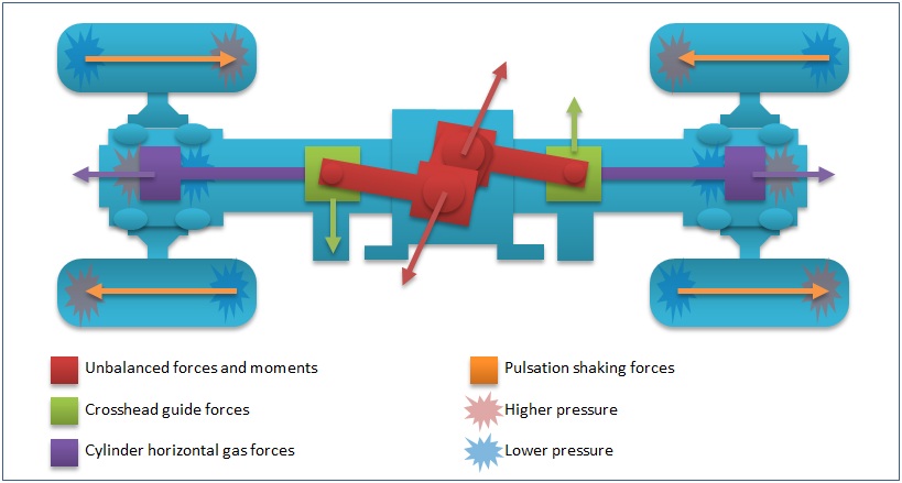 |
| Figure 5: Common Reciprocating Compressor Dynamic Forces |
8 Contact an Expert
For more information or to talk to us about a project or operational issue, email your questions to info.vdn@woodplc.com.
8 Related Services and Information
Related Pages
Tips for Managing a Successful Vibration Project • Example: Offshore Pump Package (Video) • Structural Vibration from Compressor (Example) (Video) •
Free webinar
Learn how to select and design vibration control solutions that work – using real-world data and case studies. Register now


