Services
- Static Equipment & Structures (Piping Vibration & Fatigue)
- Acoustic Fatigue Assessment for Blowdown Systems
- Acoustic-Induced Vibration (AIV) Analysis
- Finite Element Analysis (FEA) and Computational Fluid Dynamics (CFD)
- Flow-Induced Turbulence (FIT) Analysis
- Flow-Induced Vibration (FIV) Analysis
- Multiphase and Slug Flow Analysis
- Pipe Stress Analysis
- Piping Vibration and Integrity Assessment
- Review & Design Support Services
- Small-Bore Connections (SBC) Assessment
- Structural Vibration and Dynamic Design Analysis
- Subsea Piping Vibration
- Thermal Striping
- Tube Failure Analysis
- Veridian AM
- Veridian VS
- Vibration Inspection Program
- Water Hammer Analysis
- Machinery Analysis
- Bottle Sizing Service
- Compressor Package Engineering
- Finite Element Analysis (FEA) and Computational Fluid Dynamics (CFD)
- Foundation Design and Dynamic Analysis
- Fuel Gas Compressor Piping Transient Analysis
- Lateral Vibration Analysis
- Pipe Stress Analysis
- Pulsation & Mechanical Analysis: Reciprocating Compressor
- Pulsation & Mechanical Analysis: Reciprocating Pump
- Pulsation & Mechanical Analysis: Screw Compressor
- Pump RCF Analysis
- Review & Design Support Services
- Shell Transverse Acoustical (STA) Analysis
- Skid Design and Analysis
- Surge Control Design for Centrifugal Compressor Systems
- Torsional Vibration Analysis (TVA)
- Field Engineering & Troubleshooting
- Finite Element Analysis (FEA) and Computational Fluid Dynamics (CFD)
- Human Vibration
- Motion Amplification Vibration Analysis
- Noise Troubleshooting
- Performance Assessment (Thermodynamic)
- PostPro – field data processing and analysis
- Structural Vibration Troubleshooting
- Thermal Striping
- Troubleshooting, Root Cause Analysis (RCA)
- Veridian iDAC
- Vibration Inspection Program
Tube Failure Analysis
Heat exchanger tube rupture analysis as per API 521
A heat exchanger tube rupture can lead to failures in the low-pressure side of the exchanger and its connected piping system.
API 521 requires tube failures to be considered in the overpressure relief system design.
Tube failure risks and causes
Heat exchanger tube leaks – from pinhole to full rupture – can occur due to corrosion, erosion, vibration fatigue, brittle fracture, fretting (baffle chafing) or creep.
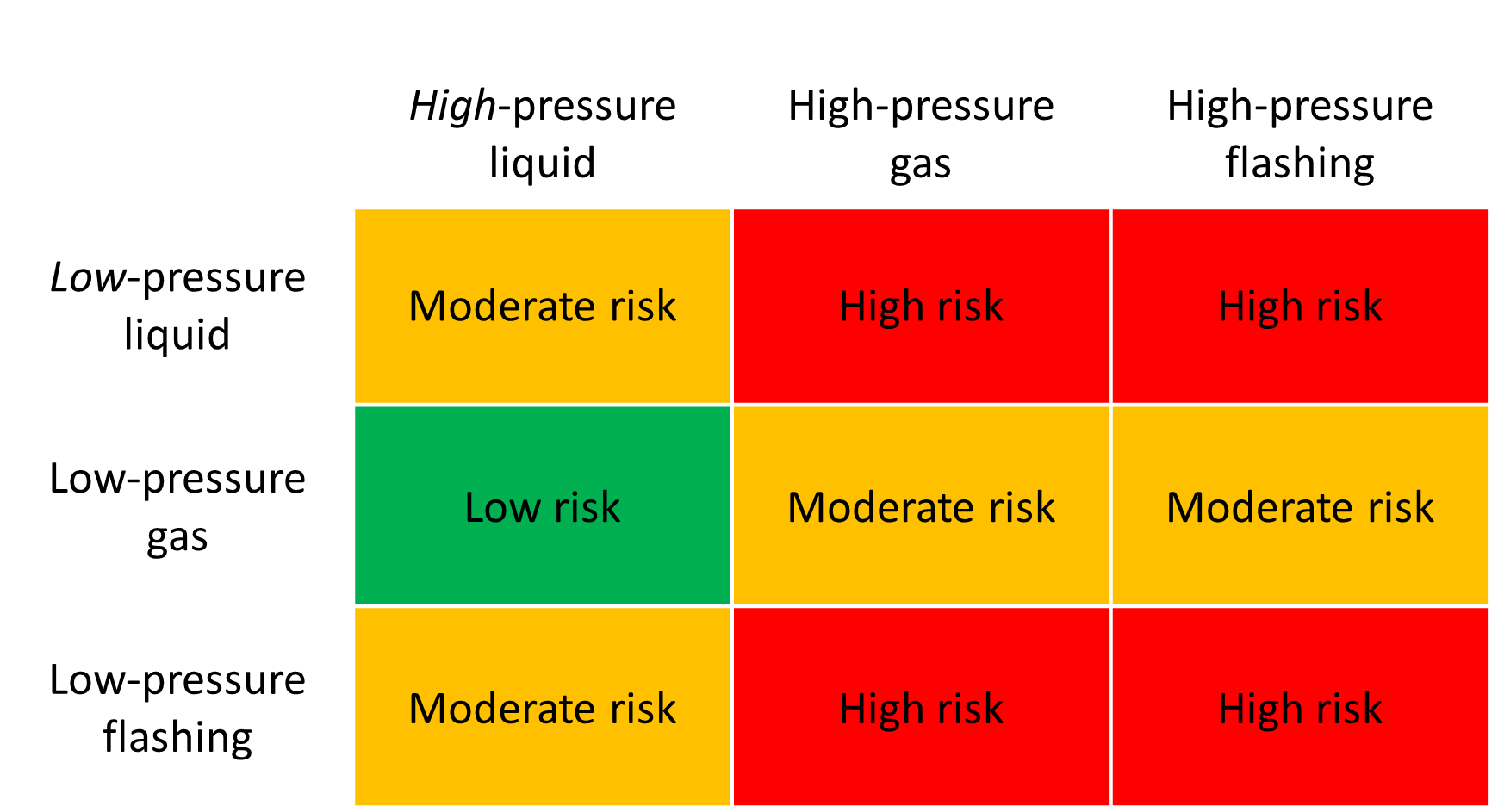
The risk of tube failure is highest when the design pressure on the high-pressure side exceeds the hydrostatic test pressure on the low-pressure side.
Pressure surge is the highest risk for exchangers with low-pressure fluids in a liquid state and high-pressure fluids in a vapor state.
Low-pressure system failure mechanisms include:
- Overpressure due to inadequate relief capacity
- Overpressure due to rupture-induced pressure surge
- Slug loading
- Flow-induced turbulence
 |
|
Heat exchanger tube failure risk factors |
How to reduce the risk of tube failures in heat exchangers
The risk of overpressure can be reduced by modifying the exchanger design, increasing the rated pressure of the low-pressure system, or improving the capacity, response time, and layout of the relief system.
API 521 and other guidance for tube failure assessments
API 521 provides guidance on how to design and maintain pressure-relieving systems for heat exchangers to minimize the risk of overpressure situations and reduce the potential for tube rupture.
API Section 4.4.14, requires the potential for tube failure in heat exchangers to be considered when designing a pressure-relieving system. The standard recommends that the maximum pressure on the low-pressure side of the exchanger does not exceed the corrected hydrotest pressure through the duration of the tube failure event. API 521 also recommends the assessment of slug flow and flow-induced turbulence, which are of particular importance as tube failure often results in multiphase relief events.
Additional guidance and requirements related to assessing tube failure are found in API 660, ASME/BPVC Section VIII, and Energy Institute guidelines for the safe design and operation of shell and tube heat exchangers to withstand the impact of tube failure.
Tube failure analysis
A tube failure analysis evaluates the ability of the low-pressure system to withstand the tube failure.
The analysis is conducted in a staged approach. First, the system is assessed to determine if exchanger tube failure presents any overpressure risk to the low-pressure system. Second, if an overpressure risk exists, the appropriate tube failure relief rate must be considered in the system design. Third, if the shell-side to tube-side pressure differential is large, the transient response to the tube failure should be considered. Transient screening and detailed dynamic modeling can be completed.
The relieving rate is typically based on a full-bore tube rupture; however, smaller rates can be used if an assessment is completed to demonstrate that full-bore rupture is sufficiently unlikely.
Slug flow and flow-induced turbulence should also be considered.
A tube failure analysis is an important part of ensuring safe and reliable heat exchanger operation, and it can help prevent equipment damage, unplanned downtime, and safety hazards.
Wood’s design approach is based on API, ASME, and Energy Institute methodology and guidance.
Wood advantages
- Extensive experience and expertise – we know what to watch for and how to do it right
- Range of analysis methods and technologies – supported by leading experts and tools
- Timely and accurate results – our size and processes allow us to deliver quick and reliable results
Analysis and troubleshooting services
Contact Wood’s integrity specialists if your system is at risk from any of the above tube rupture failure mechanisms or for application support with other heat exchanger integrity issues.
Keywords
- Tube rupture analysis
- Tube leak analysis
- Tube failure analysis
- Heat exchanger failure
- Heat exchanger tube failure
- Cooler tube failure
- Dynamic analysis
- API 521
- API 660
- Relief system
- Shell and tube failure
- Tube failure heat exchanger
- Pinhole leak
Free webinar
Learn how to select and design vibration control solutions that work – using real-world data and case studies. Register now


